HOOK
OBJECTIVE
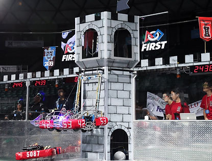
Under this system, the hook to hang on the bar to lift the 125 lb robot.

DESIGN
-
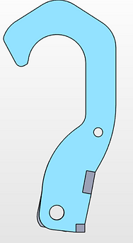
The lower half of the hook is designed to fit under the frame of the chassis and the flippers as seen on the left side of Figure 1 where the resting position of the hook is under the side frames.
-
The upper half of the hook is designed so that the center of the inner curve is aligned to the pivot point at the bottom. This will make sure that the hook does not pivot when a force or the pneumatic is deployed to climb as seen in Figure 2.
-
The hook is for an elastic band to make retracting the pneumatic easier, and the hole is placed at 27.98mm which is the farthest distance while still maintaining under the frame curve as seen in Figure 36.
-
The lower half of the hook is designed to fit under the frame of the chassis and the flippers as seen on the left side of Figure 1 where the resting position of the hook is under the side frames.
-
The upper half of the hook is designed so that the center of the inner curve is aligned to the pivot point at the bottom. This will make sure that the hook does not pivot when a force or the pneumatic is deployed to climb as seen in Figure 2.
-
The hook is for an elastic band to make retracting the pneumatic easier, and the hole is placed at 27.98mm which is the farthest distance while still maintaining under the frame curve as seen in Figure 36.
RESULTS
This was a vital component to a greater system that greatly helped the team and separate us from the rest at the competition because climbing acquired the most points, and we were the only robot at Australia and Hawaii regional that could climb.