ArboBot
OBJECTIVE
The design objective is to create a tree climbing robot capable of climbing a Kapok tree and perform wildlife observation.

BACKGROUND
The Kapok tree is a great vantage point for wildlife conservationists to observe rainforest life at all levels of the rainforest and is easier than most trees to climb on. Most tree climbing robots are either very bulky and inefficient at climbing trees, or are designed to climb only straight up on smooth bark with limited maneuverability.

DESIGN
Design Overview

-
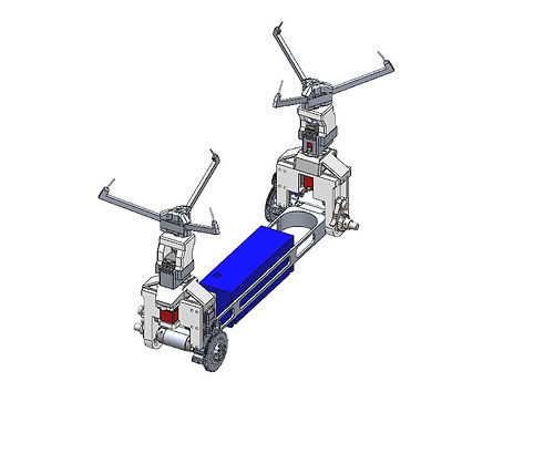
The three primary subsystems are the claw, the climbing/translational motors, and the body.
-
The claw subsystem is responsible for gripping into the bark and wood of the Kapok tree.
Each claw grips using its three spike arms actuated by a servo-mounted worm gear.
-
The climbing/translational motors subsystem contains two servo motors that are responsible for the climbing and lateral motion of ArboBot along the tree.
-
Lastly, the body of ArboBot is a structural component that connects other subsystems together and holds the payload and power source.
Dynamics and Motion
-
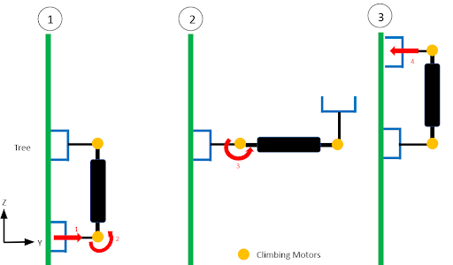
The motion of Arbobot is a self-swinging motion where it will attach the top claw, then detach the bottom to swing the bottom claw upwards.
-
The Arbobot is also capable of swinging left to right to translate and avoid obstacles such as branches
-
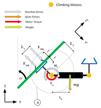
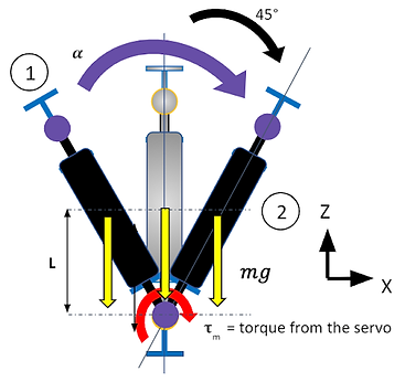
Free body diagrams were drawn to indict the required forces and torque that occur during the swinging or translating motion. This helped us find appropriate motors and gearboxes.
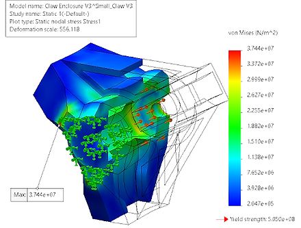
Claw Enclosure Design


-
The claw enclosure holds the worm gear with two thrust bearings front and back.
-
Material: High Strength Aluminum 7075-T6
-
To prove that the enclosure will hold the reactionary force of 2563.4 N from penetrating the wood. FEA simulation was performed on the enclosure itself.
-
Force: 2563.4 N was applied on the inner surface where the thrust bearing interacts with the enclosure
- Results:
-
Yield Strength: 505 MPa
-
Maximum Stress: 37.44 MPa
-
-
The enclosure is capable of withstanding the reactions force of 2563.4 N from the claw
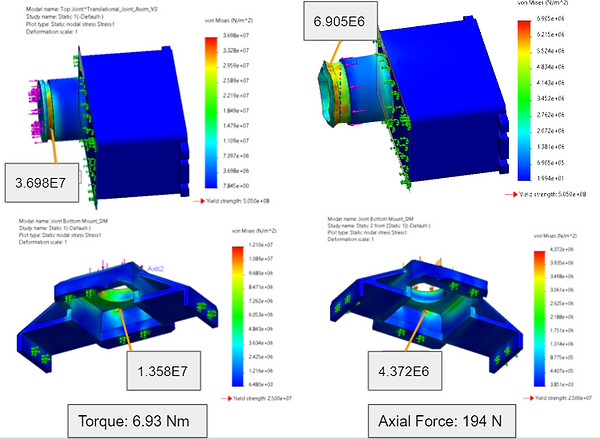
Top & Bottom Joint Design

-
The top and bottom joint allows the ArboBot to translate.
-
Material: The top joint is High Strength Aluminum 7075 T-6, and the bottom joint is ABS
-
The top and bottom joint experiences torque and axial force, so both forces had FEA simulations.
-
The results show the top and bottom joint will not yield under both the torque from climbing and axial load from the claw.
-
Both top and bottom need to handle the torque from the climbing motor and the axial load from the claw.
-
Fixtures: Fixed geometry is applied on the mounting holes and bottom of the servo mount
-
Results:
-
Top
-
Maximum Stress Torque: 36.98 MPa
-
Maximum Stress Axial: 6.905 MPa
-
Yield Strength: 505 MPa
-
-
Bottom
-
Maximum Stress Torque: 13.58 MPa
-
Maximum Stress Axial: 4.372 MPa
-
Yield Strength: 25 MPa
-
-
The results show the top and bottom joint will not yield under both the torque from climbing and axial load from the claw.
RESULTS
The Arbobot is capable of climbing an incline of 45 degrees with a maximum speed of 6.94 cm/s, carrying a payload of 1 kg, and recording 5.21 days of wildlife. These specifications surpass the current solution by offering a better balance between speed, payload, and maneuverability. Because this is a remote project, Arbobot was never built, but it was rigorously tested for structural integrity with multiple FEA simulations.
